Advice from students who prepped a custom chip
for fabrication
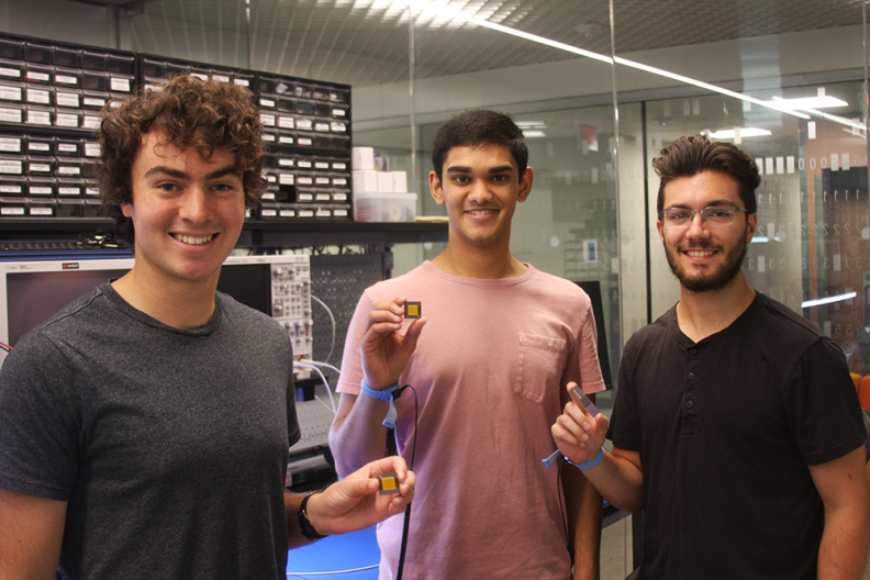
(Pictured left to right: Kyle Infantino, Dilan Lakhani and Jack Brzozowski. Photos by Eric Laine except where indicated.)
What does it take to design a microchip from scratch, prepare it for the foundry, and get a functioning microcontroller back? Students working with Cornell ECE Professor Christopher Batten are finding out, and they have some advice to pass on.
Jack Brzozowski, Kyle Infantino and Dilan Lakhani started work on their chip design as undergraduates and turned it into their Master of Engineering project. All three will graduate from the M.Eng. program this year and start jobs with major chip makers Apple and AMD. Working on the chip tapeout, they say, absolutely helped them get those jobs.
“This was really good experience for getting a job in chip design/verification,” Lakhani said. “Not a lot of students are fortunate enough to go through the whole tapeout process.”
“Interviewers could ask us anything and we’d have something to say about it,” Brzozowski added. “We could say, when we did our tapeout, this is what we did.”
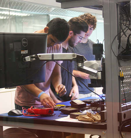
(L-R) Lakhani, Brzozowski and Infantino at work in the Computer Systems Lab in Rhodes Hall.
Their project was to design a microcontroller, test its many components, and prepare the design to be sent to a foundry to fabricate 40 tiny silicon microchips, a process known as a tapeout. The chips were “packaged” by the manufacturer, meaning they came back attached to pins that allow for connections to other devices. After further testing, they were thrilled to find their efforts were successful.
“We actually did have a design bug,” Lakhani said, “but we were able to fix that in software, so we were kind of lucky with that. Other than that, everything works as expected.”
“Creating a tapeout takes the right kind of students—enthusiastic, driven and well-organized,” Batten said. “This unique design project enabled Jack, Kyle and Dilan to learn deeply about the entire computer systems stack from transistors to logic gates, from processor design to low-level programming, and how to integrate all of this into a complete embedded system.”
It’s rare for students, especially undergrads, to have an opportunity to work on an actual tapeout and produce manufactured chips. After this team’s success, and under the guidance of Professor Batten and the Computer Systems Laboratory, more students will have this opportunity, and Brzozowski, Infantino and Lakhani have some advice.
1. Stay organized.
As you’re moving through iterations in your chip design, you’ll end up with many different versions of almost the same thing. If you’re not organized, someone will be testing a new component, while somebody else is adding new features to the design. Now there’s two versions of the same chip.
“It can be kind of confusing, understanding which is the most up to date,” Brzozowski said. “We did use GitHub, but I think we could have done it in a cleaner way, where the versions are more tucked away into their own branches.”
The team learned to keep files laid out such that everybody knew which version was the most current, so things didn’t get out of sync. “That’s why we put this tip at the top of the list because that’s really easy to do if you’re not careful, especially with bigger project teams,” Brzozowski said.
2. Check for inferred latches.
3. Check for hold time violations.
4. Don’t forget synchronizers.
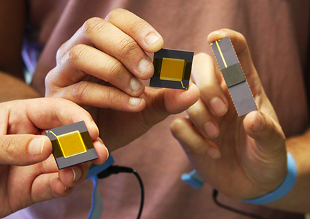
The team's chip, shown in two different packages.
These three pieces of very technical advice all have to do with logic timing and how chips will store and access values over the time it takes to perform its function. The tools engineers use to design chips will often add design elements automatically when user code is ambiguous, and designers need to watch out for this.
“Sometimes these tools will do things, like create an inferred latch,” Infantino explained. The synthesis tool, which takes code and turns it into gate level design, may infer that a latch is needed and insert it into the logic. The design tools provide reports and logs, but the volume of them can be so great that it’s easy to get lost. Designers need to check that each component is in the place where it’s supposed to be.
“You really need to be careful and look through the logs to make sure the tool isn’t doing anything you didn’t intend for it to do,” Infantino said.
5. Make checklists that multiple people are responsible for reviewing before sending off the tapeout.
Chip design is a complex, time-consuming process, and chip fabrication requires a substantial investment of money. If you miss something simple, like a typo, the chip may not work at all. Double checking, even triple checking, is essential, the team said, because the stakes are high and the consequences of an error in your tapeout could be devastating.
“To spend $10,000 and get a dud back is a waste of everyone’s time and money,” Infantino said. The team made exhaustive lists of potential pitfalls that needed to be checked before proceeding to the tapeout and ensured that team members checked each other’s lists. The things that should go on your checklist are the things that are easy to check, but also easy to forget, they said.
6. Add Design for Test components to add visibility into the chip.
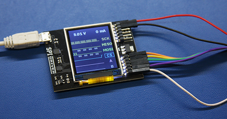
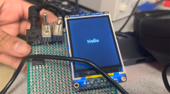
This SPI driver module allows the team's host computer to communicate with the chip.
Design for Test (DFT) refers to adding features to a chip that make it easier to diagnose errors that arise while testing the chip in silicon. “For our chip, the goal was to add visibility by having a few extra, smaller components that would give us data about what’s going on inside,” Infantino explained. “If we have no DFT components, we’ll have no idea where we went wrong if a test fails.”
DFT components don’t add any functionality to the chip. Rather they create windows into individual components or processes for designers to observe their behavior in isolation. “We can basically cut off the rest of the design and say, we’re only testing this right now,” Brzozowski said.
The DFT components helped the team locate a design bug. “We were able to check which modules worked and ruled them out as the source of the problem,” Lakhani said.
7. If something looks fishy, it probably is. (Ask questions and raise concerns.)
“The tools do so many weird things if you don’t tell them exactly what to do,” Brzozowski said. “You really want to make sure that if something looks a little wrong, you don’t just say, 'I’m sure the tool knows what it’s doing.'”
Being very explicit with design instructions is essential. Chip design tools are very sophisticated, the team explained, and the problems they are trying to help designers solve are very complex. Sometimes it’s just not coming up with the optimal solution because the optimal solution is hard to find.
“The tools will spit out huge logs with tons of warnings,” Infantino said. “You need to figure out which warnings are okay to ignore, and which ones aren’t.”
8. Think about power distribution.
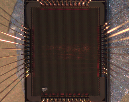
The team's chip viewed through a powerful microscope. The red lines in the center are a glimpse of the logic gates of the processor within the chip. (Photo provided.)
If you put all the power pins in one corner, trying to push current through one small, dense area, it’s possible for that area to get too hot. You could fry a chip by having too much current. But the main reason to distribute power across a chip is maintaining voltage.
“The primary concern of having all the pins in one corner is that the logic all the way on the opposite corner will see a non-negligible drop in the voltage due to current flowing through long, resistive wires,” Brzozowski said. The chip is only about 2.5 millimeters wide, but even at that scale the consequences of a voltage drop can be substantial.
The difference between higher and lower voltage is what the chip’s logic uses to determine a bit’s value. When voltage is lower than ideal in one section of your chip, the logic could misinterpret whether a particular bit should be a one or a zero, a phenomenon known as bit flipping. Maintaining an even power distribution across the chip helps ensure the logic will function properly.
9. Use your resources.
This is a reminder to reach out to people who might be in a position to help with problem solving. This tapeout project began several semesters ago when Brzozowski, Infantino, and Lakhani were undergraduates. Over that time, they sought advice from a number of experienced experts.
“Our advisor, Professor Batten was really helpful steering us in the right direction, as well as telling us who to go to for different issues,” Infantino said. They consulted with other student teams in Batten’s group “to show us what mistakes we were making.”
Getting advice, and in some cases getting tools and components from students who had previously completed chip tapeouts, was in keeping with the spirit of collaboration in an open- source hardware ecosystem valued by Batten’s group. “We had to get some resources from the University of Washington to help with the memory generation, and our ASIC flow was built using a framework from a group at Stanford,” Infantino said.
“They were also super helpful because they know how difficult this is,” Brzozowski said, “and now we know how difficult it is.”
10. Don’t expect something to work if you didn’t explicitly test it.
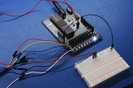
The team's chip mounted on a printed circuit board for testing.
Testing applies to every stage of the design, and that’s maybe the most important piece of advice for prepping a tapeout.
“There are parts of our design that are a little repetitive,” Infantino said. “We have eight GPIO pins. We implemented them all the exact same way. One of them works so there’s no reason the other ones wouldn’t. But you can’t make assumptions like that; you have to test each one.”
Brzozowski elaborated: “You’re pretty confident the processor works because it’s passing all your tests. But when you put it into a larger design and connect it to other components, you can’t just say I already know the processor works and move on. That’s kind of dangerous.”
The team explained that issues can emerge when you place functioning components into a new context. “That happens a lot. You need to test them together,” Infantino said.
Danielle Regis ’15 M.Eng. ‘16 jokingly calls herself an “engineer who talks too much.” In reality, she’s someone who uses her outstanding communication skills to shatter expectations around how...
Read more about Danielle Regis inspires students to ask “Why?”
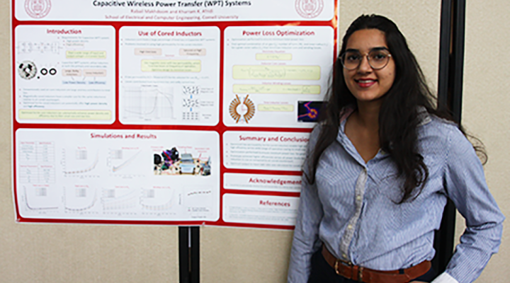
The ECE M.Eng. Poster Session was held in the Duffield Atrium on Tuesday May 2, 2023. A total of 47 posters were presented by students over the course of two sessions, morning and afternoon. All...
Read more about 2023 M.Eng. Poster Session Winners
Last semester's ECE 4760 Digital Systems Design Using Microcontrollers course with Lecturer Hunter Adams was focused on the Raspberry Pi Pico microcontroller. In the final segment of the course, the M...
Read more about Projects that make Hunter Adams say "Wow!"